As a part of my career review, I would like to introduce the project that I presented as Bachelor’s Final Project. The main idea was to design and implement a library to generate interactive urban environments running in the browser using WebGL through the library three.js.
I decided to start this project for the following reasons: firstly, at that time I was working on Artificial Intelligence, and I wanted to step out of my comfort zone, even more considering that in my Bachelor programme we just had had one introductory subject about Computer Graphics (CG). Secondly, I have always thought CG as a fascinating area of Computer Science, since you can create, visualise and interact with everything that you can imagine with CG, i.e: M. C. Escher would have loved Echocrome.
Considering these, I faced the challenge of learning WebGL/three.js. As regards the programming language, three.js is implemented (surprise) in JavaScript, so this would be my first significant project using it.
My idea is publishing some posts talking about different parts of the process. In this case, I am going to focus on the geometry and its generation, leaving interaction, collision detection, texturing, and other issues for future posts. About the code for this project, it could be found in my GitHub, and a “demo” here (multitouch devices are not supported).
Introduction
At that time, there were different approaches to cope with the procedural generation of a city, some of them are summarised in Kelly, G., & McCabe, H. (2006). Among all these techniques, I wanted to follow a similar idea to the grammar-based approach.
The first idea of the project was to develop an engine for generating the urban environment creating and using one of those grammars, but I focused on finishing the functionality, and the generation process ended up following arbitrary rules. I could have substituted those rules for the ones that a formal grammar provides, but due to time constraints, I left the random ones.
Summing up the generation, I divided the whole process into three parts: City’s layout generation, Buildings’ layout generation, and 3D geometry generation.
The gist is the following: first of all, the city layout is generated considering certain restrictions (size of the city, height/width of the roads, the number of them, etc.), resulting in a set of polygons which represent the base of an apple. Secondly, these polygons are the input for the next procedure that generates one building’s layout for every polygon and, finally, these 2D polygons are “elevated” to give them a 3D shape. I am going to describe, briefly, these parts in the following sections.
City’s layout generation
Regarding the creation of the initial layout, the algorithm divides iteratively the polygon that defines the city. This division is performed horizontally and vertically, with the random height and width that are initially assigned. Some of these sections are carried out diagonally to generate a more realistic layout. The following figure illustrates this process.
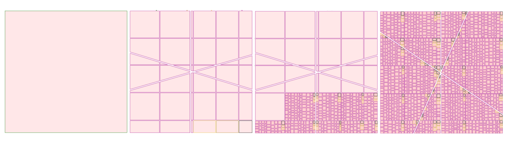
As regards polygons’ manipulation, it is performed using GPC, a general polygon clipper library in its JavaScript version. As a result of this step, we obtain a set of polygons where each one defines a block. Regarding this, I included during this process the concept of districts for the first divisions. Consequently, we could generate different kinds of neighbourhoods: residential, financial, squares or green areas. The next step takes these polygons, and it will create the building layout.
Generating buildings’ layout
From this point, we have polygons that define blocks. With this blocks, we represent the sidewalks, and by reducing them, the initial building layout. I implemented the following decision tree to assign the type of building that will accommodate the block.
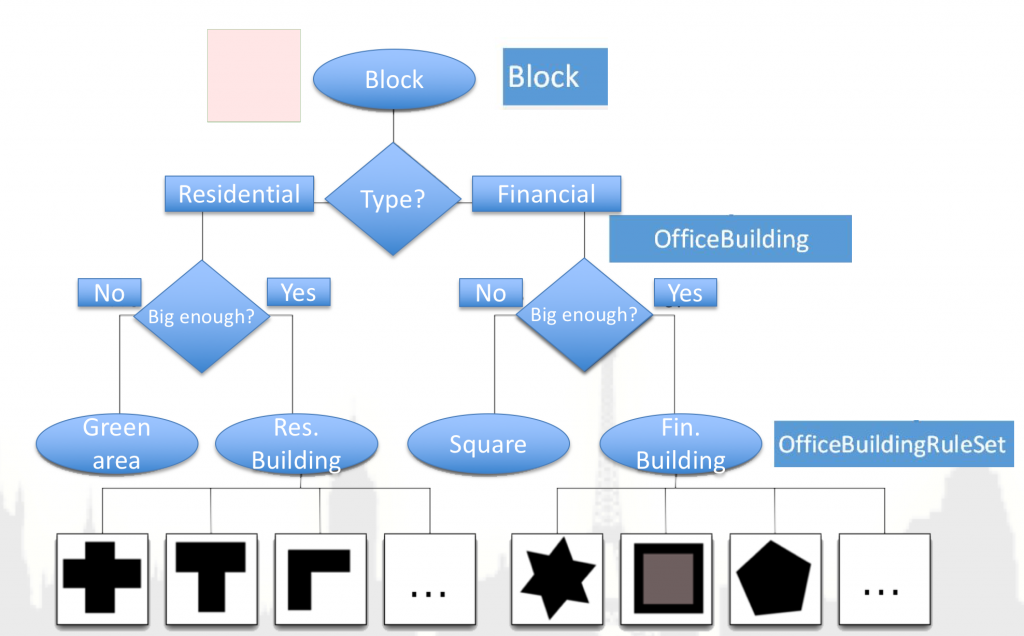
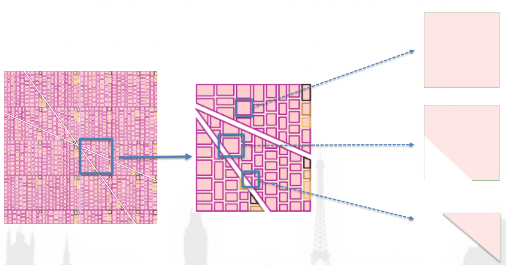
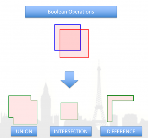
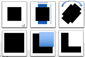
At this step, we could choose different sets of rules for every kind of building. As regards these rules, they are, in general, polygon transformations as it is shown in the following figures.
When the building layout is defined, we are prepared for providing volume to the buildings. However, as I mentioned before, the shape of the structure depends on the decision tree’s output. Therefore, if there were assigned a green area to a specific block, it would be decorated with trees and grass. Thus, performing this implies that could exist blocks without buildings.
Providing the third dimension to the buildings
Once we have the polygon that defines the “blueprint” for the building, we just need to “elevate” the shape. As a polygon is a set of ordered points in a 2D space, we can generate the 3D geometry following the steps that are shown underneath this paragraph. Usually, this procedure is called “extrusion”.
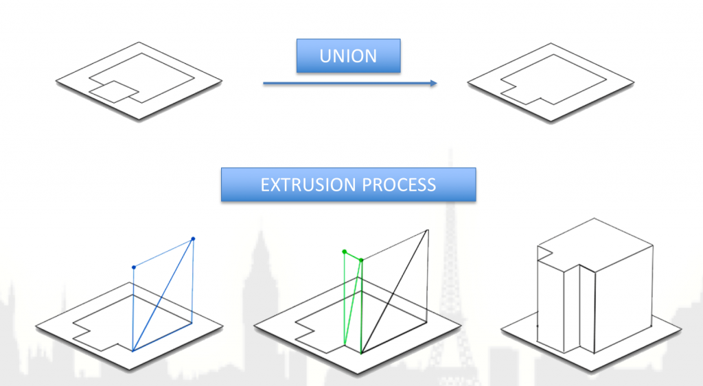
It is important to note that we can repeat this extrusion as many times as we want. Doing this, we could obtain buildings with different heights, scaling the shape during the process.
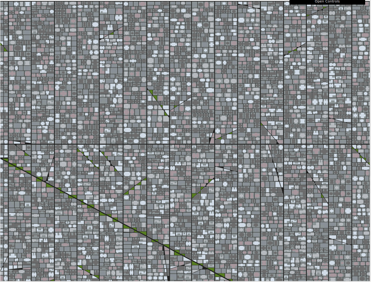
Once this step has finished, we have created all the geometry and we can enjoy our beautiful city.
An example of a city layout: